
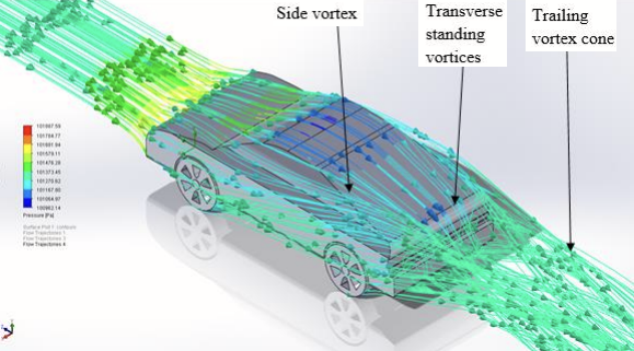
A rear wing does not receive the same airflow on every car. The roof, rear window and body sides have already changed the air’s speed and direction before it reaches the wing. The base car therefore sets the conditions in which an aerodynamic package must work.
Our earlier articles examined vehicle performance, yaw and boundary layers. Here, we bring those ideas together through three common rear-body shapes: fastback, notchback and squareback. Their different flow patterns explain why a package that suits a GT coupé cannot simply be transferred to a hatchback.
Three shapes, three flow patterns
For this comparison, consider three cars with broadly similar front sections but different rear profiles. This helps us examine what happens when air leaves the roof and returns towards the space behind the vehicle.
- Fastback
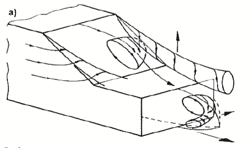
- The roof continues into a sloping rear surface. Many sporting coupés use this profile. The slope can guide air towards the tail, but its angle and curvature determine whether the flow stays attached.
- Notchback
- A distinct rear window leads down to a separate, more horizontal boot deck. A conventional saloon is the familiar example. Flow can separate above the rear window and reattach on the boot.
- Squareback
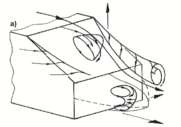
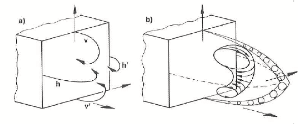
- The roof ends at a steep, nearly vertical rear surface. Estates and upright hatchbacks approach this shape. Air separates at the roof and side edges, leaving a broad wake behind the car.
 View full size ↗
 View full size ↗
 View full size ↗
These are aerodynamic categories. Hatchback describes the rear opening, so a hatchback can have a sloping fastback profile or a much more upright squareback profile. Real cars also combine features from these simplified shapes.
The wake is the disturbed flow behind the car. Separation, recirculation and rotating flow structures called vortices affect the pressure on the rear body. A large low-pressure rear region commonly increases pressure drag. However, wake size alone cannot tell us the complete drag or lift force.
Fastback: manage the rear slope
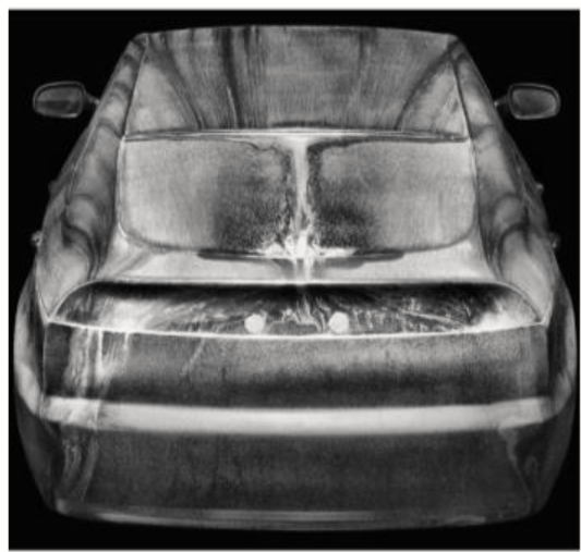
A gradual rear slope can help pressure recover as the air moves towards the tail. This can reduce the pressure difference between the front and rear of the car. If the slope demands too much pressure recovery, the boundary layer can separate instead. The resulting drag depends on the slope, rear edges and surrounding flow.
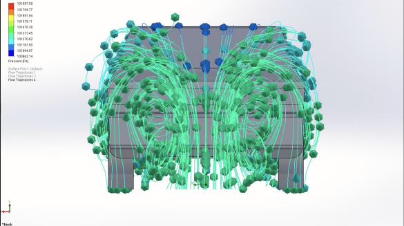
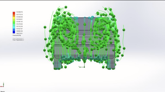
Air also moves around the rear roof pillars, known as the C-pillars. Vortices from these regions interact with the flow over the rear window. The fastback trajectories in the opening image show that a smooth-looking body can still produce a complex wake.
A fastback does not automatically produce downforce. Low pressure on an upper rear surface can contribute upward lift as well as rearward drag. The direction depends on the surface orientation. The net load comes from pressure and friction over the complete car, including its underside.
 View full size ↗
What this means for the package: the wing can receive downward-directed flow from the rear slope, with different conditions near the C-pillar vortices. Its local angle of attack can therefore differ from its mounting angle relative to the chassis.
A rear spoiler can change the pressure and separation over the tail, reducing rear lift in a suitable design. A wing needs a height, position and incidence selected for the actual incoming flow. A diffuser must be developed with that wing and the body wake, because pressure near its exit affects the underbody flow.
Inspect the fastback wakeRear-view flow trajectories
 View full size ↗
Notchback: control flow above the boot
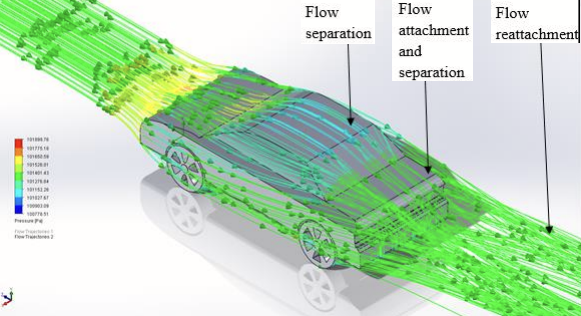
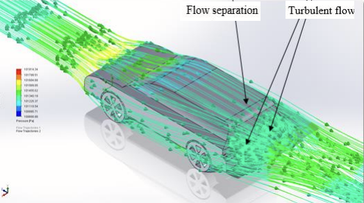
The step from roof to rear window creates a different problem. Flow can detach near the roof edge, pass over a recirculating region and then reattach on the boot deck. Whether it reattaches, and where, depends on the rear-window angle, boot length and C-pillar geometry.
 View full size ↗
The labelled flow trajectories show separation and reattachment for this example. They describe a possible notchback flow pattern, rather than a fixed behaviour for every saloon.
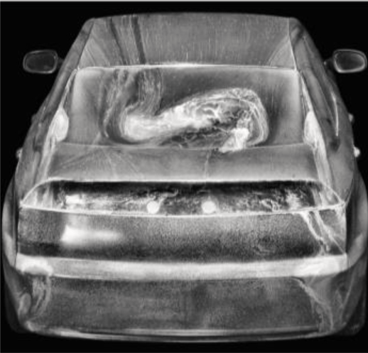
The surface traces below show a strong difference from the fastback: the rear-window flow is less uniform and includes a recirculating pattern. A wing placed low over the boot may sit partly inside this disturbed region. It can then receive less local air speed and more variation in flow direction than its designer assumed.
 View full size ↗
The package must account for the separation region. A boot-edge spoiler can alter the deck pressure and final separation point. A wing may need to sit above the separated region, with its height confirmed by flow measurements or CFD. Increasing the wing angle alone may add drag without recovering the expected load.
Vortex generators ahead of separation are another possible tool. They mix faster outer air into the boundary layer and can delay separation. Their size and position matter, and they add drag themselves. They are useful only when the change to the complete car is beneficial.
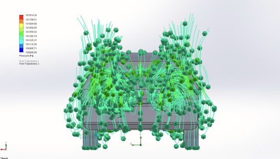
Inspect the notchback wakeRear-view flow trajectories
 View full size ↗
Squareback: manage abrupt separation
On an upright rear body, the air cannot follow the sharp turn down the back of the car. It leaves the roof and side edges, forming shear layers around a large recirculating wake. Low pressure on the rear face contributes to pressure drag.
 View full size ↗
The squareback example has a clear roof-edge separation and a disturbed rear region. The rear-view trajectories show how the roof, sides and underbody feed that wake.
A squareback can avoid some of the lift associated with suction over a long rear slope. That does not guarantee zero lift or stable handling. Roof pressure, underbody flow and axle load distribution still matter. The wake can also switch between asymmetric states, even when the incoming flow is nominally straight ahead.
Start at the roof edge and the wake boundary. A roof spoiler can set the departure direction of the upper flow. A rear wing needs to reach suitable flow around or above the separated region; its relation to the roof edge can be more useful than its height above the ground alone.
Small changes to the rear side edges or taper can alter wake pressure and drag. They must be assessed together with the roof device. A diffuser also discharges into this same rear region, so it cannot be designed independently of the upper-body wake.
Inspect the squareback wakeRear-view flow trajectories
 View full size ↗
Experimental work on a squareback automotive shape shows why a time-averaged, nearly symmetric wake should not be mistaken for an unchanging flow.
What the drag numbers tell us
The comparison uses the following broad drag-coefficient ranges. They illustrate a possible progression from a gently sloped rear to an abrupt rear face. They are teaching ranges, not results from three matched test cars or limits for each body type.
| Rear shape | CD range | Main rear-flow question |
|---|---|---|
| Fastback | 0.25–0.30 | Does flow remain attached down the slope? |
| Notchback | 0.30–0.35 | Where does separated flow reattach on the boot? |
| Squareback | 0.35–0.45 | How do the roof and side shear layers set base pressure? |
Drag forceD = ½ρU²CDA
Here, ρ is air density, U is air speed relative to the car and A is reference frontal area. At equal speed, density and area, CD = 0.40 gives about 45% more drag than CD = 0.275. Those are selected midpoints from the ranges, so this is an illustration, not a measured penalty for choosing a hatchback.
The extra drag reduces the force available for acceleration and increases the power needed at a given speed. Frontal area also matters: a lower coefficient does not guarantee lower drag if the car is substantially larger.
A controlled example shows why the body label is insufficient. In Wieser and colleagues’ DrivAer wind-tunnel tests, the zero-yaw drag coefficients were 0.258 for the fastback and 0.254 for the notchback. The notchback was slightly lower in that setup, despite the ordering suggested by the broad ranges. Those quarter-scale tests used a smooth underbody, stationary wheels and a fixed ground arrangement.
Stability means more than low lift
Lift changes the load carried by the tyres. If rear lift increases while front load changes little, the rear tyres have less normal load and the handling balance can move towards oversteer. A greater loss of front load can instead favour understeer. The actual response also depends on the tyres, suspension and operating condition.
We therefore need the front and rear axle-equivalent aerodynamic loads, not just total lift. A pitching moment describes the tendency to rotate the car nose-up or nose-down. Its sign has meaning only after the axes and moment origin are defined; a negative value alone does not establish stability.
 View full size ↗
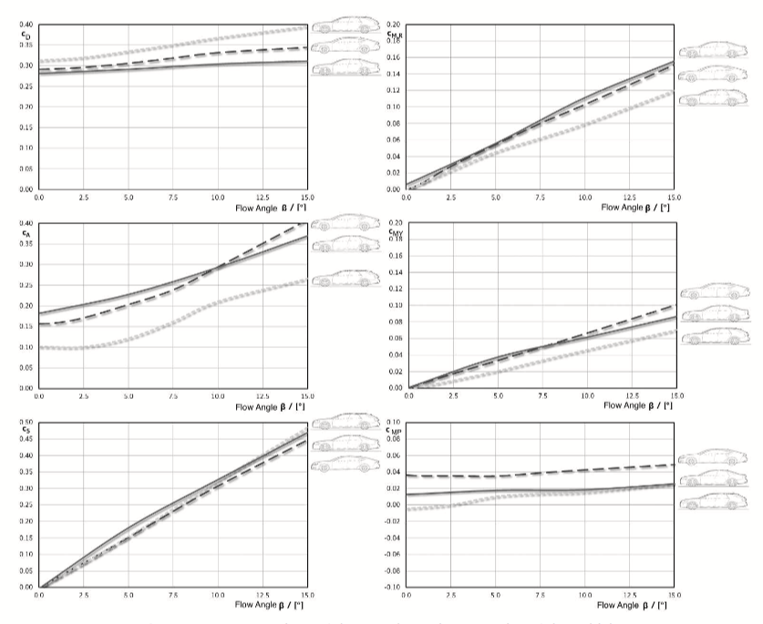
Reading the comparison. The six panels show drag, lift, side force and rolling, yawing and pitching moments against flow angle from 0° to 15°. The example curves show that the shapes differ in both their starting values and their response to yaw. The small labels are retained in the original figure; open it at full size to inspect them. These curves are a separate comparison from the illustrative ranges above.
Crosswind creates side force and a yawing moment, which tends to turn the car about a vertical axis. The force location and the change with yaw matter. A low straight-ahead drag coefficient, or a low total lift coefficient, cannot by itself identify the car that will be easiest to control in a gust.
There is also a difference between a steady load and a stable response. To assess aerodynamic stability, we need to examine how forces and moments change with yaw, pitch, ride height and time. The useful objective is adequate tyre load and a predictable balance across the conditions the car will experience.
Tailor the package to the complete car
A wing’s force depends on the local flow. As a simple illustration, a 10% reduction in incoming air speed reduces local dynamic pressure by 19%, because 0.9² = 0.81. With wing area and force coefficient held constant, its load would fall by the same amount. In real separated flow, the force coefficient can change as well.
This is why a wing tested in uniform air cannot be assigned the same performance after it is placed behind any roof. We need the speed, flow angle and variation across its span at the intended mounting position.
| Rear shape | Upper-body priority | Package check |
|---|---|---|
| Fastback | Rear-slope attachment, downwash and C-pillar vortices. | Wing incidence in local flow; spoiler, wing and diffuser interaction. |
| Notchback | Rear-window separation and boot-deck reattachment. | Wing clearance above disturbed flow; boot spoiler and possible separation control. |
| Squareback | Roof-edge separation, side shear layers and base pressure. | Roof spoiler and wing position relative to the wake; diffuser discharge. |
The front end must then match the rear package. A splitter changes front load and underbody supply. Wheel wakes and cooling exits affect the flow farther downstream. Adding rear downforce can move the aerodynamic balance rearwards, so the complete car needs reassessment after each major change.
A diffuser expands the underbody flow passage and recovers pressure towards its exit. A well-designed system can sustain low pressure farther upstream. Too much expansion or unsuitable incoming flow can cause separation. It is therefore inaccurate to treat every diffuser as a device that simply accelerates air through its entire length.
Start with a baseline flow map, identify the load or drag problem, and test the proposed parts together. Then repeat the useful comparisons at relevant yaw angles and vehicle attitudes. This connects the body shape to a package that works over an operating range.
From GT circuits to rally stages
A fastback GT car: develop the roof, wing and floor together
A fastback-style GT car, such as the Porsche 911 GT3 R, offers a sloping roof and rear body that shape the approach flow to its wing. The design task is to position and set the wing for that flow while managing rear lift and maintaining the required front-to-rear balance.
For the 992-generation car introduced in 2022, Porsche describes a raised forward underbody, smooth undertray and rear diffuser. It also uses a swan-neck wing mount to keep the wing’s lower surface less obstructed. Porsche links the underfloor layout to reduced pitch sensitivity. This is a useful example of body, floor and wing being developed as one system.
An upright rally hatch: work with the roof edge and rear wake
An upright hatchback-style rally body places its rear wing much closer to the flow leaving the roof edge and the boundary of the rear wake. The package therefore puts particular emphasis on the roof-to-wing path, separation direction and the flow reaching different parts of the wing during yaw.
The Toyota GR Yaris also shows why the categories are not absolute. It is a hatchback, but its roof slopes and tapers. Toyota’s 2020 body-design explanation states that this shape was chosen to increase the airflow reaching the rally car’s rear spoiler. The body was changed to suit the aerodynamic device, just as the device must suit the body.
Rally use adds another constraint: larger changes in ride height, pitch and yaw, together with rough surfaces and ground-clearance needs. A low circuit splitter and floor cannot simply be transferred to that environment. Rally cars still use underbody aerodynamics where the rules and vehicle layout permit, but their useful operating range differs from that of a GT car.
Body shape explains the different starting flow; competition rules and operating conditions explain further differences in the final package. GT cars are not all fastbacks, and rally cars are not all squarebacks. Booted rally saloons also need the notchback treatment discussed above.
A fastback package must manage flow down the rear slope. A notchback package must account for separation and possible reattachment above the boot. An upright hatch or squareback package must manage the roof-edge shear layer and broad rear wake. The real-world lesson is the same: choose the base shape and aerodynamic devices together, then verify the complete car’s loads and balance under the conditions in which it will run.
Figures and further reading
The flow images are retained at their original resolution and credited to their original sources. They illustrate flow mechanisms; they do not establish the performance of a McCarbon vehicle or a proposed race package.
Rear-flow schematics: Mayer, W. and Wickern, G. (2011), The New Audi A6/A7 Family — Aerodynamic Development of Different Body Types on One Platform, SAE International Journal of Passenger Cars – Mechanical Systems, 4(1), pp. 197–206. doi:10.4271/2011-01-0175.
Flow-trajectory images: Bappa, M. (2015), Aerodynamic Simulation of Vehicle Bodywork Design. The colour scales differ between images; use these views to compare flow structure, not exact pressure values.
Surface-flow images and DrivAer comparison: Wieser, D., Schmidt, H.-J., Müller, S., Strangfeld, C., Nayeri, C. and Paschereit, C. (2014), Experimental Comparison of the Aerodynamic Behavior of Fastback and Notchback DrivAer Models, SAE International Journal of Passenger Cars – Mechanical Systems, 7(2), pp. 682–691. doi:10.4271/2014-01-0613.
Six-panel aerodynamic comparison: Schuetz, T. (ed.) (2016), Aerodynamics of Road Vehicles, 5th edn, SAE International. Further examples are linked beside the squareback, Porsche and Toyota discussions.